Plan Section Elevation Drawings Symbols 1 2
How to Describe Elevations from Floor Plans

This elevation drawing tutorial volition show you how to describe elevation plans required by your local planning department for your new home design.
We will explain how to draft these drawings by manus. If you lot are using habitation design software, near programs take a tool to create the elevation plans from your design.
House top drawings are created after you accept created your floor plan drawings. See our Brand Your Own Pattern tutorial for instructions on creating detailed floor plans. If you are just starting out with your abode blueprint, check out our complimentary Domicile Blueprint Tutorial.
What are Elevation Plans and How are They Used?

Once you have completed cartoon your detailed floor plans, you lot'll yet need to create a few more than construction drawings. In addition to the floor plans, you will need to provide your builder and local planning department with acme drawings and cross-section drawings.
The meridian plans are scaled drawings which show all 4 sides of the home with all perspective flattened. These plans are used to give the architect an overview of how the finished habitation will expect and the types of outside finishing materials. It will as well provide information about the elevation of the basis on the diverse faces of the dwelling house. For the local planning department, they will need these drawings to insure that the local building code is being adhered to.
Y'all volition be creating iv summit views, one for each side of the house (regardless of whether your home is of a conventional shape or not). Usually these drawings are drawn to a scale of one' : 1/4". Bank check with your architect and planning department equally to what scale they prefer these drawings to exist.
For each side of the house, pinnacle drawings should show:
- Each wall length and its height,
- The roof width and summit,
- The visible portion of the foundation,
- Any exterior features (such equally decks, porches and stairs),
- Window and door trim,
- Eavestroughs,
- Exterior wall and roof finishings (e.g. wood siding on exterior walls, asphalt shingles on roof)
- The finished ground level.
Materials Required
For a list of the required drafting materials run into our page on drafting house construction drawings. Aside from a adept straight edge, an builder's scale volition be very useful.
Getting Started

To typhoon your elevation plans, you will start with your floor plans for the main floor of your business firm. The easiest method is to draw your elevations to the aforementioned scale as your flooring plans. To brand the process a scrap easier:
- Tape your principal flooring plan cartoon to the surface of your work table with the front end side of the house facing towards y'all.
- Tape the sheet of paper for your elevation drawing just below or to a higher place the floor plan.
With this method you will transfer each feature on the front face of the house to the other sheet of paper.
The drawing to the right shows a completed height cartoon and the floor program it was taken from. The dotted lines bear witness places where the walls bump in or out.
Step past Step Guide to Drawing House Elevations
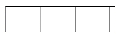
Drawing Main Floor Wall Baseline

To depict the initial baseline for the main floor,
- Using your floor program drawings and starting at the extreme left end of any walls on this side of the house on the footing floor, measure out the horizontal distance of this wall. Make sure you lot are including the thickness of whatever siding cloth for the exterior side walls for this level. This siding can exist very sparse in the case of parging or thick in the case of stone or brick.
- Draw a faint line the same length of this wall towards the lesser left third of your page. This faint horizontal line will later exist erased since it will not be visible from the outside of the business firm (unless the exterior cease of the house changes at this verbal point). It is fatigued now only as a reference from which to measure to the top of the next floor or roof line.
- Make a small-scale upward tick mark at the finish of this wall.
- If there is another outside wall at the aforementioned superlative to the right of this wall (for example a wall that bumps out or recedes in from this first wall), measure this wall in the same way every bit the first.
- Draw this next line as a continuation of the outset line. Do not erase the tick mark that indicates the division between these walls.
- Continue on marker walls in this mode until y'all attain the end of walls on this side of the business firm.
Determining and Drawing Wall Heights
Adjacent you will draw the vertical lines for the outside walls on this side. For each of the wall bases:
- Determine how high the wall will be above its unfinished flooring elevation. To do this you will demand to consider the meridian of the ceiling of the rooms within this department of the house and add together to that the peak of any floor or ceiling joists above it. Also add on the height of whatever sub-flooring, if in that location are floors above.
- Draw faint vertical lines upward from each of the wall base of operations lines to the pinnacle you have determined in the previous stride. (After y'all will draw a darker line which includes the finished fabric on the outside of the home.)
- Draw a faint horizontal line at the level of the upper ceiling joists or subfloor higher up this level.
- If there is another floor in a higher place this level, continue on to the pace five. Otherwise move on to the next section, Draw Window and Door Outlines.
- Using the flooring plans for the next level up, perform steps ane through three again making tick marks where you will demand to describe any vertical walls. Again determine the heights of these walls and so draw a faint horizontal line to show the level of the top of the sub-flooring or ceiling joists for the next level.
- Continue repeating the above steps until you have no floors above the electric current level. So move on to the next section, Draw Window and Door Outlines.
Draw Window and Door Outlines
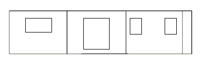
For all of your windows and doors, measure from the horizontal lines of your floors to position the exterior doors and windows. Your construction drawings, unremarkably the cross-sections, volition item the height at which each window should be placed. A carve up window and door schedule gives the dimensions for all your windows and doors.
At this point, using your architect's scale for accurateness, draw just the outline of the window and door outside dimensions to the aforementioned scale as your walls, floors and roof. Later on you lot will depict the exterior window and door trim.
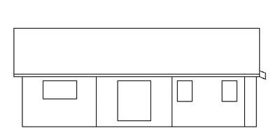
Drawing the Roofs
The roof lines can be of many styles: gable, shed, hip, gambrel, etc.
To describe the roof for each peak view, first consider whether your roof volition overhang and drib below the exterior wall on the elevation plan yous are currently drafting. For a shed or gable roof with eaves, the roof on two sides will drib lower than where information technology connects with the wall. From the view of the other two sides information technology will stay at i level. Have a look at the elevations at the very meridian of this page to see an illustration of this.
Dropping Roofs
If this level has an overhanging roof that slopes downwards over the wall, you volition need to practise some calculations for roof overhang before y'all draw the horizontal line for the wall acme.
If there is a roof overhang at this level which drops down over the wall, calculate how much the roof volition drop in the actual overhang expanse. To do this,
- Have the slope or pitch of your roof, which is usually described equally the rise over run in the form of 5:12, six:12, xiv:12, etc. The offset number refers to how many inches (or centimetres) the roof will rise (or drop) over a horizontal distance indicated by the second number (which in N America is usually 12 inches).
- Take your horizontal roof overhang to make up one's mind what the vertical roof overhand drop will be. For instance if you lot have a five:12 roof pitch and a 12 inch horizontal roof overhang, the roof will driblet a total of v inches. If your horizontal roof overhang was 18 inches, the roof would drop 18/12 x 5 = 1.five ten 5 inches = vii.5 inches.
- Now you will need to subtract this drop from the superlative of the wall that you previously calculated since in the elevation drawing this roof line will drop below the top of the wall summit. Using this new calculated peak, draw the line showing the lower edge of the roof line.
Not-Dropping Roof Lines
For an stop gable wall or a shed wall, determine the highest point of the wall below your roof. To do this you need to know the slope of the roof. First read the section above on roof pitch, then calculate the height of top most bespeak of your roof in a higher place the electric current floor in the following manner.
- Measure the horizontal altitude from one of the side walls of the business firm in this top view to where the superlative of the roof will be. For some houses this volition be the center of the firm, for other roof styles information technology may not be the centre. We'll call this Distance to Peak.
- Then calculate Distance to Superlative x Roof gradient where roof slope is the rise/run. For instance for a 5:12 roof gradient and a distance of 13 anxiety the acme for the peak of the roof (above the electric current floor) would exist: 12 feet ten 5 / 12 = 5 feet.
- Marking a tick on the floor surface to indicate the spot higher up which will lie the roof peak. Extend a faint vertical line upward from this point.
- Measure out upwardly this line to the tiptop you accept just calculated above.
- At present bring together this roof peak to the outside border of the house.
- If the roof slopes direct down to the other side of the house you can describe another line from the roof top to the other edge of the firm too.
Side by side make up one's mind the thickness of your actual roof including all framing and the roof itself and describe this onto your superlative drawing.
Make sure that you have included all roofs that are visible from this house face. Notice in the pinnacle above, the small portion of shed roof which covers a bumpout on the right side is visible.
Basements, Foundations and Chimneys
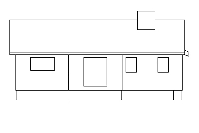
Next add on the basement, crawl space or foundation. For the elevation views you lot need only show the parts of this level which are visible higher up basis. Other drawings, called cross-sections, will provide further building details for this part of the home.
For the lower level or foundation, showtime determine if the lower wall, without whatsoever finished surface such as siding or stucco, volition protrude from the upper wall. So consider what type of finishing volition be on the foundation and what will be on the upper levels. For some homes the concrete foundation may have parging or stucco and the upper level(south) may take a dissimilar finishing. If the whole house will have the same finish type hopefully your home design is such that the lower foundation wall is flush to the upper wall(due south). If non, now is the fourth dimension to adjust your foundation plans then that they will be affluent.
If the sidings will change, consider whether yous want them affluent, the finished foundation wall protruding, or inset. In that location is no correct fashion to do it simply in general an inset foundation wall could give your home a somewhat unstable look. If you are edifice a traditional wood framed abode y'all have a bit of latitude equally to where on the thick foundation wall you will set up the wood framing for the floor above. In this manner you can decide exactly how your upper finished walls will or will not line up.
In one case you have determined where the foundation wall volition sit, depict a faint line from the principal floor downwards to slightly beneath what you recollect will be your finished basis height.
At present you can too add together any chimneys. As with the walls you lot have fatigued, make sure that yous include the thickness of any finishing materials that may be on the chimney, be it wood siding, brick or rock.
Detail Exterior Finishing

- If you will have woods or another type of siding (horizontal, vertical or cedar shake) draw these lines to bespeak the end. For a stucco wall you lot need not draw any surface. For a brick or stone wall, the finish should be drawn. Make sure you include any trim bands, belt lines, etc.
- Using your architect's scale, draft in all window and door trim as well as item any window or door lites, and exterior knobs or handles.
Decks, Porches and Railings and Finished Basis Level
- Now draw in whatever decks or porches, their railings and stairways. This can be fiddly work, peculiarly drawing the railings. Use your scale to make certain your drawing is authentic.
- Then add on any other architectural features such as fascia, gutters or downspouts.
- Next do an accurate measurement of what you programme to have as the difference of your primary floor height to the final level of the landscaping around the house. This may be fairly flat around the whole business firm or it may leave a portion of the basement or foundation completely above basis with another function almost completely cached.
- Draw this finished landscaping line along the walls of this elevation view.
- Finally, clearly characterization the drawing to indicate verbal finishing materials to be used on exterior surfaces, this includes roofing materials and siding.
Repeat this process for the other three sides of the domicile.
As with the floor plan drawings, information technology is necessary to include a title cake on the folio which specifies the firm name, the date, and the calibration used. The title block is mostly in ane corner of the drawing.
Next House Structure Drawing Tutorial
Check out the adjacent design tutorial module: Cartoon Cross Sections.
No part of this spider web site may exist reproduced or copied without written permission. Illegal Internet copies will exist detected by Copyscape.

Source: https://www.the-house-plans-guide.com/elevation-drawings.html
0 Response to "Plan Section Elevation Drawings Symbols 1 2"
Post a Comment